Experts tell you that the six characteristics of the computer control pipe bending machine you need to understand
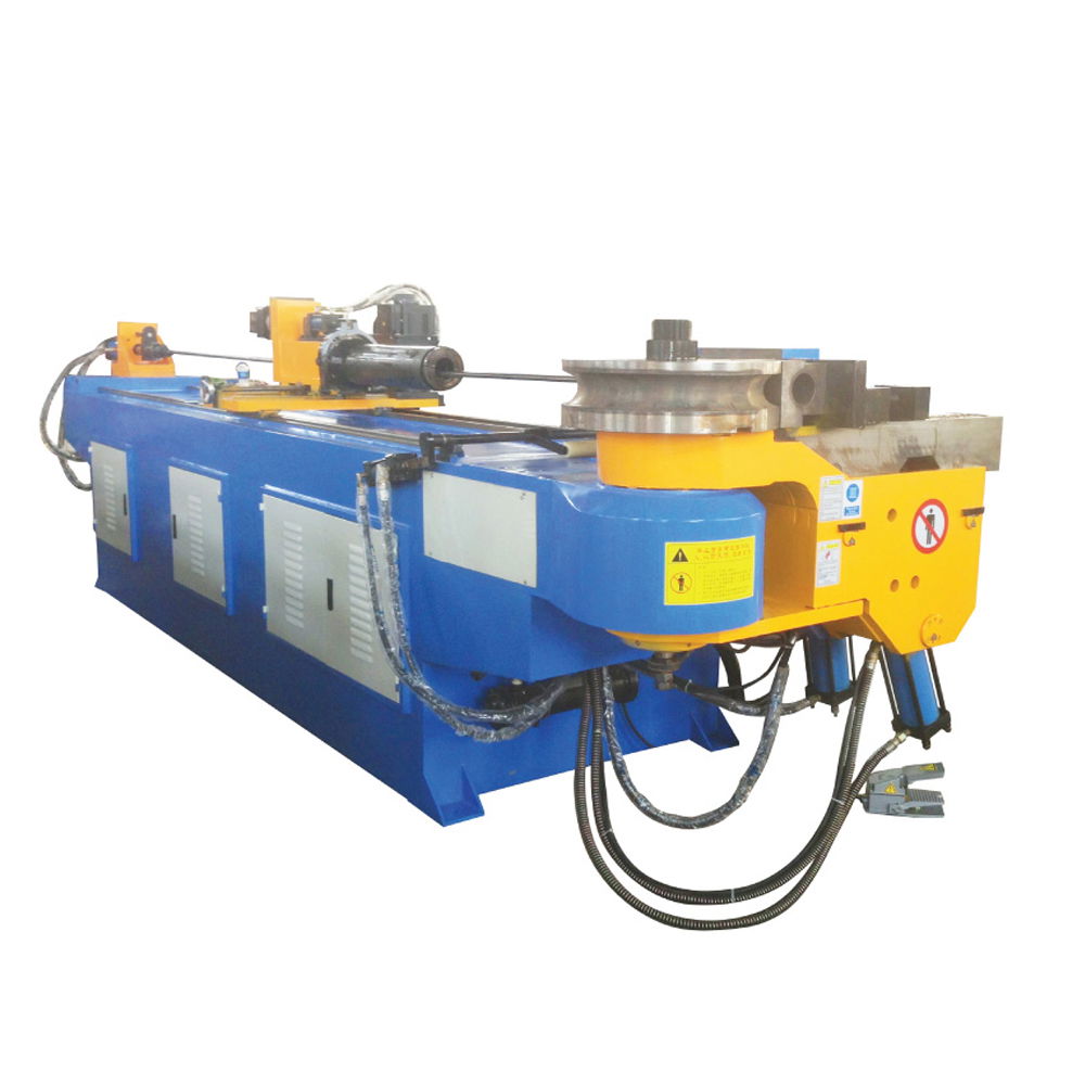
The application of tube bending machine is widely known and can be used in sheet metal, hardware products, steel structures, precision machinery, auto parts, glasses, jewelry, nameplates, advertising, handicrafts, electronics, toys, packaging and other industries. The tube bending machine uses a metal laser with a xenon lamp as an excitation source to output a high-energy-density laser beam, so that the area irradiated by the spot on the workpiece is partially melted and vaporized instantaneously, and the automatic cutting is realized by a computer controlled numerical control mechanical system moving the spot irradiation position. High-tech equipment integrating laser technology, numerical control technology and precision mechanical technology. But do you know the six characteristics of using a computer to control a pipe bending machine? Taiwan and mechanical experts tell you:
1. The elbow head can be moved laterally along the guide rail. This is necessary after pipe and tube bending machine is adjusted to adjust the bending slot of the machine to the center line of the machine. This is simpler than adjusting the machine centerline with the guide rails and tailstock on the adjustment bed.
2. The trolley that completes the straight-line feeding movement (DBB) is pulled forward by the tube during the bending process of the tube. In this way, the "positive thrust" is removed, thereby eliminating the synchronization problem between the trolley and the bending speed, and removing the DC motor negative feedback system for increasing the "positive thrust", simplifying the electrical circuit. Since the positive thrust is advantageous for the bending of the pipe, especially when bending a pipe having a large diameter, a positive thrust is necessary. Thus, the VB bender adds a booster.
3. When bending, as the trolley acts as a load, it is pulled forward by the pipe. In order to improve the bending, the wall thickness of the curved portion of the pipe is prevented from being excessively thinned, the rebound is reduced, and the boosting device is added. When bent, the stamp not only compresses the tube, but is also urged forward by the thrust to form a side thrust that assists the bend.
4. The elbow arm and the bending main shaft are integrated, the curved bending mold shaft can be replaced, and the clamping mold moves up and down. This not only has a reasonable structure, but also increases the mechanical part strength, and the structure is simple, so that the electric circuit is also simplified.
5. When feeding the last bend, the car may collide with the die. At this time, the “interference zone” function can be used, that is, the die is returned → the car continues to feed → the bend arm returns → the space corner (POB) → the clamp Clamping → The chuck is loosened, the trolley exits the interference zone → the stamper is pressed → the tube is bent. In this way, the curved pipe not only avoids the collision of the trolley with the stamper, but also ensures the smooth completion of the last bend, and can reduce the clamping loss of the material head and reduce the production cost.
6. The bed is welded and simple and compact.